Sunday, November 24, 2024

Yes, it's SUPPOSED to sound like that: my modified version of the Synthrotek DIRT filter


 While I personally refuse to make the jump to the Eurorack/500/modular gear universe, I am not against appropriating some of the more common sounds that exist there. Especially the ones that can be easily modified to work with a negative center +9v DC power supply.


I found this one on Synthrotek's site - the schematic I have included is lifted from the build doc for this modular filter kit that they sell under the name "DIRT". It's technically a low-pass filter with a whole lot of noisy possibilities. The resonance and bias are highly interactive with each other AND the cutoff control.


I modified their layout slightly, subbing a 1n4001 for the polarity protection diode (they call for a 1n4148 - which has a similar forward voltage drop) as well as eliminating the battery clip, adding an input pull-down resistor (1m to ground on the input) and a master volume potentiometer.


I tested the CV input using an Electro Faustus Dual Oscillator, and it made this thing stutter and bubble like crazy.


Once again - all credit is due to Synthrotek for the design + schematic on this one and if you use Eurorack units, you should buy a kit from them and build it. But if you want to make a super-noisy, unpredictable low pass filter for use in stompbox format - I can't recommend this one enough.


Thursday, November 14, 2024

It's just a bypass switch. That's it. My version of the Demedash Incandenza clickless relay stomp.


 This is another layout that I posted over at Dirtbox but it is most definitely the thing I build+use more than anything else I make. It's a version of the Demedash Effects Incandenza relay bypass on/off switch that Steve Demedash came up with a few years ago.


No microcontroller required, super-low parts count, and absolutely no mistriggering. My stripboard drawing has pads marked for all four leads that come out of your standard true-bypass circuit: send, return, +9v, ground. So you can just slap this on to any circuit that you desire, that uses a true-bypass switch. Polarity protection is included on the switch daughterboard so you can omit that from the main circuit, too.


The relay is 5 volts, dual pole/dual throw, and non-latching. There are a couple other versions of this schematic floating around out there but this contains one pretty important edit from Steve Demedash himself: the 100 ohm resistor that is placed between the 555 chip and the relay itself. This limits the juice that the relay receives, as the chip puts out about 8v and the relay is rated to 5v. I've listed three different model relays on the drawing itself (and I may have mentioned a 4th - the Panasonic one - on the schematic), but just about any relay of the same size can be subbed provided you check the pin out and datasheet. All of the relays I have listed have a coil impedance of about 175-180 ohms. If the relay you want to use has a higher or lower value, you may need to raise or lower the value of the 100 ohm resistor on the layout, too.


I realize that building an entirely separate board for the on/off switch is something that a lot of folks may not want to do. But if you ALL READY like giving yourself a hard time by working on strip/vero, why not go the extra mile for a switch that is much more reliable than a mechanical 3PDT?

Saturday, October 26, 2024

The AionFX/Traynor TS-50B preamp - CAN YOU DO ANY LESS??!!


 BUILDERS NOTE: MAKE SURE THAT YOUR ELECTROLYTIC CAPACITORS ARE RATED MINIMUM 35 VOLTS.

This layout is posted over at Dirtbox, but it is one of the best damn bass preamps ever, so I wanted to put it up here, too. 

To be clear - I did not draw a majority of this one. Anders/Fuzzhead did all the heavy lifting on this but he used an LTC1144 charge pump to create the bipolar power that this thing needs. While that chip takes DC voltage and does a really good job of converting it to +/- AC voltage, it only puts out about 20 milliamps of current.


Unfortunately - this preamp circuit needs WAY more. Like up around 100mA, if I'm not mistaken. So while the LTC1144 IC works, you will get a subtle, ever present whine from the supply.


AionFX, who did the schematic for this originally (it is one of their PCB projects, go buy one) suggests a kind of expensive (about $10-$12 each) power converter that does the trick, though.


So my layout takes Fuzzhead's drawing and incorporates that power converter, as well as the Zener diode and inductors it needs, and now this thing works perfectly.


Seriously - it's the loudest, clearest bass preamp EVER (and sounds great on guitar, too) and, dialed in right, you can get that characteristic Traynor TS-50B clang that just cuts through anything and everything. The first time I plugged mine in I was like "oh there's THAT bass tone" Jesus Lizard, Shellac...


Friday, October 25, 2024

If you've got room for two more knobs, you put some wobble on that echo with a PT2399 modulation daughterboard


 I designed this using the schematic from 1776 Effects Multiplex Delay modulation add-on board. I changed a few of the values but this is about 95% that design (credit where it is due). Also, I originally drew this for a fellow builder named Ben Spinks, who was actually the one to build and verify this first.


This is meant to be paired with the trails-bypass PT2399 circuit from my previous post but will work with just about any delay circuit you plug it into. However - the resistor connecting to lug 3 of the depth pot may need to be raised or lowered depending on how much wobble you want. I included the values for 1776's original design on my drawing, as well as my preferred ones.


You can place an SPST toggle between the mod board output (depth lugs 1+2) and the delay board in (usually delay lug 3 or lugs 2+3) in order to make or break the connection between the two, effectively turning the modulation on or off. The same "make or break" SPST toggle could also be placed on the 9v connection lead so that the modulation LED goes dark when the modulation is switched off. Untested, but it should work...


But this is not really necessary since the last 1/4 turn of the speed/rate pot makes the modulation so fast as to be inaudible. However, I realize some folks may want the option to "kill" it completely so I mention it for that reason.


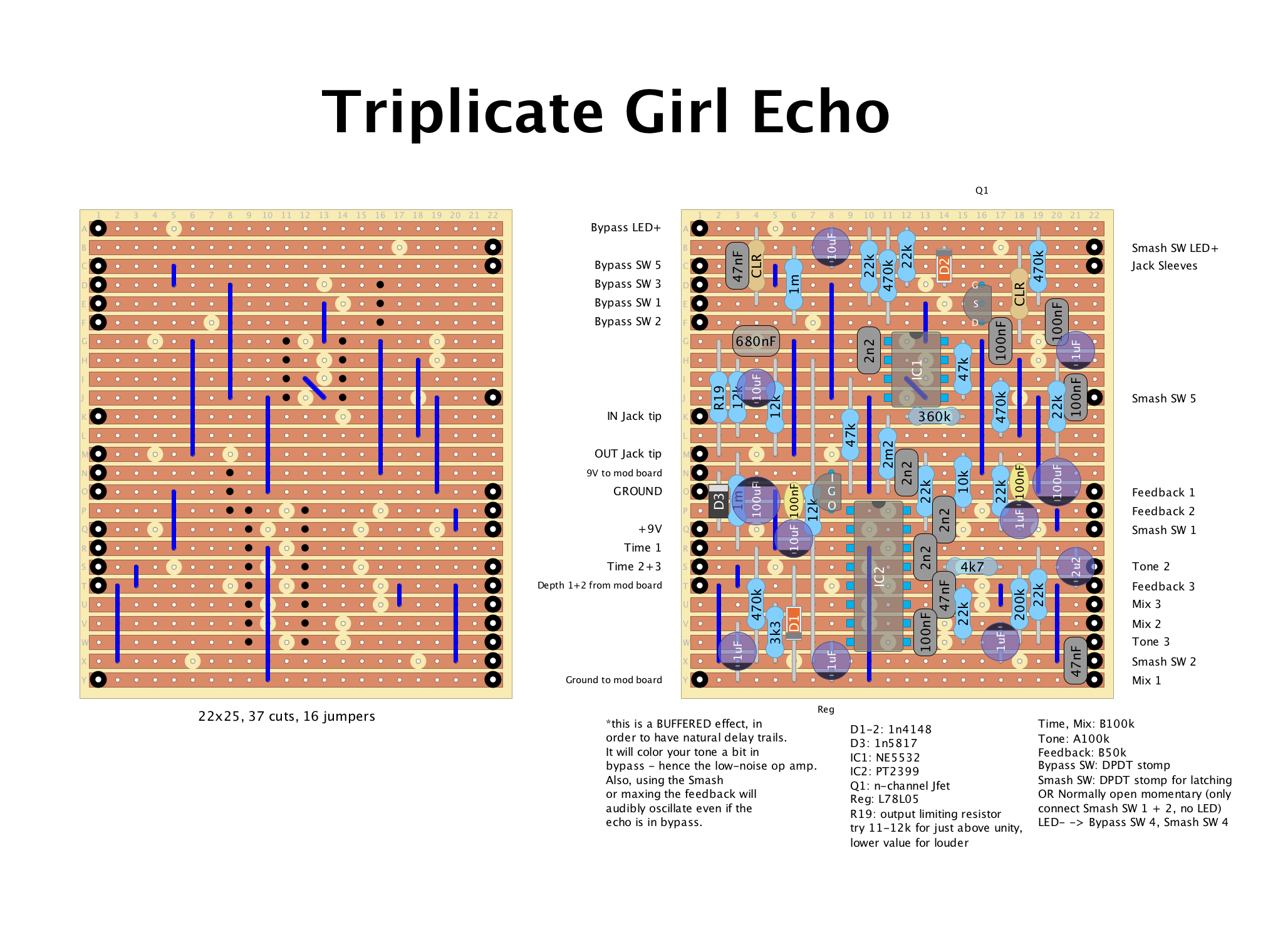
My FIRST post - a PT2399-based delay circuit with buffered/jfet trails bypass switching

 Okay everyone - I've been mulling over just how I want to proceed with sharing my stripboard drawings and such since I abandoned Instagram. Which I really needed to do - the dopamine manipulating algorithms were just too damn much for my sometimes fragile mental state and I've really been doing so much better since giving Zuck the heave-ho.


I'm going to start posting here occasionally, and even though it is quite clunky to do from my phone, I think that will keep me from overdoing it - as opposed to just putting every half-baked idea that falls out of my f*cking skull up for the whole internet to see.


So this is the first thing I have decided to show off. It is based on the layout for the original Catalinbread Montavillian delay. I, like many other DIYers out here have tried A TON of PT2399 delay circuits and as endearing as the limitations of the echo chip are, I've found that most of the pedals that use it are either WAY too clean and filtered OR overburdened with that digital "puttering" that happens when you try to coax more than 500ms of delay time out of the PT2399.


The Montavillian has a quite a lot of EQ+filtering but still sounds quite close to analog/BBD. It is just dirty enough to pass for something MUCH more expensive. 


I doubled the delay time of the original and, altho you can hear the repeats start to get a little ragged, there are none of the aforementioned puttering digital artifacts present. 


Which is why I could add the jfet/trails switching and not worry about unwanted noise bleed. EDIT: I should have noted this on the layout, but I used a PN4393 for the switching, try a 2N5457, J201, etc. So this circuit is NOT true bypass. In addition to coloring your tone a little, the feedback/smash functions remain active at all times and will oscillate audibly when maxed, even with the circuit bypassed.


I also wired the tone pot the other way around, so that the repeats get brighter, not darker as you turn the knob clockwise. There are a few more notes on the actual picture itself about output resistor values and different ways to wire the "Smash" switch - which is an on-demand runaway feedback control.


I'm going to be posting the mod board addition that I did for this soon.

I'm probably an idiot. But no new posts for a while until I figure this out...

 To anyone reading this: I got a new phone a couple weeks ago and can't seem to find the permission setting that allows Blogger to see m...